
Overhead Door Closer: Identify, Measure and Replace It
Identify a surface or concealed overhead closer, measure its preparation, and match its power, arm, handing and safety requirements.
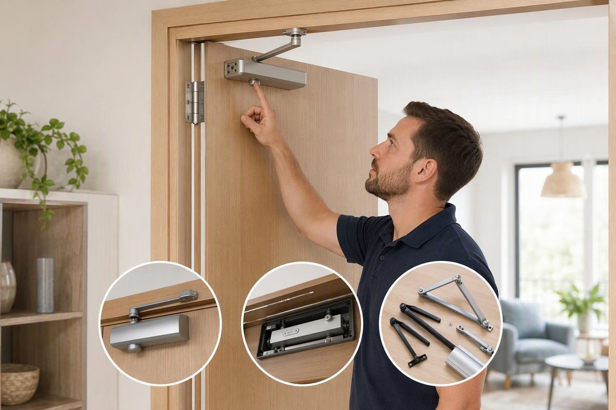
An overhead door closer may mean either a visible surface closer near the top of a door or a closer concealed inside the head frame or door. Establish which type you have before measuring: the two types do not share a universal footprint, arm or door preparation.
- Surface-mounted closer: The rectangular body and articulated arm or track are visible.
- Overhead concealed closer: The body is recessed into the frame head or top rail of the door; usually only an arm, track or cover plate is visible.
Concealed closers can require very specific cavities. LCN’s concealed range, for example, includes models for a 4 × 4-inch (102 × 102 mm) aluminum frame tube, a 1¾ × 4-inch (44 × 102 mm) tube, or installation inside the door itself (LCN concealed-closer catalog). Similar-looking cover plates do not establish compatibility.
Identify the mounting first
For a typical surface closer, inspect the closed door from the side carrying the hardware.
| Mounting | Closer body | Arm shoe or bracket | Common reason for the arrangement |
|---|---|---|---|
| Regular arm | Pull-side door face | Frame face | Straightforward mounting where a projecting arm is acceptable |
| Top jamb | Push-side frame head | Door face | The door’s top rail cannot accept the closer body |
| Parallel arm | Push-side door face | Underside of frame head | The arm sits relatively close to the door when closed |
These names describe mounting geometry, not interchangeable accessories. Parallel-arm installation may require a particular shoe or bracket. Narrow top rails, shallow frame faces, deep reveals, blade stops and flush ceilings may also require model-specific plates or spacers. LCN’s 4000 Series catalog, for example, gives different minimum surfaces and accessories for hinge-side, top-jamb and parallel-arm arrangements (surface-closer mounting details).
For a concealed closer, determine whether the body is in the frame or door. Then identify whether the opening uses butt hinges, offset pivots or center pivots, and whether the arm is a single-lever track arm or a double-lever arm.
Record these details before ordering
Do not dismantle a concealed assembly merely to identify it. Remove a decorative cover only as the manufacturer’s instructions permit.
- Manufacturer and complete model number. Photograph the body label, mounting plate, arm, track and any stamped handing mark.
- Door hand and swing. Record the hinge side and whether the door swings toward or away from each face. Some closers are non-handed; others require a right- or left-hand unit. LCN’s 2030 instructions, for example, say the closer hand stamped on the mounting plate must match the door (2030 installation instructions).
- Door dimensions. Measure width, height and thickness in inches and millimeters. Note the door material, glazing and unusually heavy construction.
- Application. Record whether the door is interior or exterior, its traffic level, and exposure to wind, weather or building-pressure differences. Door width alone does not settle spring-power selection.
- Existing preparation. Measure fixing holes center to center, horizontally and vertically. Record the body and mounting-plate dimensions separately.
- Available mounting surfaces. Measure the top rail, frame face, stop depth, reveal and clearance to ceilings or trim.
- Hinge or pivot geometry. Identify butt, continuous or swing-clear hinges, or the pivot type. The applicable template may locate the closer from the hinge or pivot centerline.
- Arm and function. Record regular, parallel, track, hold-open or stop-arm construction. Note the required opening angle and whether a separate door stop is present.
- Labels and wiring. Photograph fire-door labels and any wiring for an electric holder, detector or releasing device before work begins.
A tracing of the existing holes can help compare preparations, but the selected model’s template or dimensional drawing controls. Mounting dimensions can change the arm preload and maximum opening angle; LCN’s 4040XP instructions use different dimensions and setup steps for different mountings and opening angles (4040XP installation instructions).
Match the replacement in this order
- Closer family and mounting type
- Door and frame preparation
- Handing, swing, and hinge or pivot arrangement
- Spring-power range for the actual door and application
- Arm function and opening angle
- Required listings, accessibility performance and fire-door compatibility
- Finish and cover style
An adjustable-power closer is not automatically suitable for every door in its nominal range. Use the sizing chart for the exact closer and mounting. Manufacturers may specify different sizes for interior and exterior doors and may call for greater power where strong drafts exist; reduced-opening-force settings may also be insufficient to close and latch some doors reliably (LCN concealed-closer sizing tables).
ANSI/BHMA A156.4 covers surface-mounted, in-door, overhead-concealed and floor-concealed closers. Its conformance criteria include cycle, operational, closing-force and finish tests; a Grade 1 closer must complete 2 million test cycles (BHMA A156.4 overview). Grade does not show that a closer matches the existing holes or satisfies every requirement of the opening.
Adjust only after the door moves freely
Before increasing spring power, check for loose or worn hinges, a dragging door, binding seals, strike misalignment and pressure problems. Do not use the closer to overcome a poorly aligned door.
After installation, follow the instructions for spring power, main speed, latch speed and backcheck. Backcheck cushions opening movement; it is not a door stop. Do not open an adjustment valve farther than the manufacturer permits. LCN warns that opening regulating valves too far can cause leakage, personal injury or property damage (4040XP instructions).
Where the U.S. ADA Standards apply, a closer must take at least 5 seconds to move from 90 degrees open to 12 degrees from the latch. The federal standard also limits continuous opening force to 5 lbf (22.2 N) for covered interior hinged doors; fire doors use the minimum opening force allowed by the appropriate administrative authority (U.S. Access Board, 404.2.8 and 404.2.9). A low opening-force setting must still close and latch the door reliably.
Treat a labeled fire door as an assembly
Do not wedge a fire door open or add an ordinary mechanical hold-open arm. NFPA explains that fire doors must remain closed and latched or be arranged to close automatically during a fire, and that blocking or wedging them open is prohibited (NFPA fire-door guidance). Product restrictions can be more specific: LCN states that hold-open tracks must not be installed on fire-rated doors in its 2030 instructions.
Confirm the closer, arm, fasteners, preparation and any electrically released hold-open system against the opening’s labels, manufacturer instructions and applicable local requirements. For apartment-entry context, see self-closing door requirements. A matching hole pattern alone does not establish fire-door, egress or accessibility suitability.